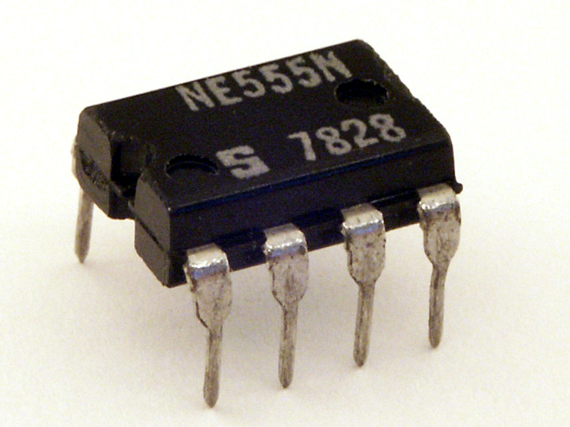
Signetics NE555N, the original 555 type oscillator, in a dual-in-line plastic package, manufactured in 1978 (work week 28). Author: de:User:Stefan506.
The idea[]
It was to create a variety of timer for electronic timing, pulse generation, and oscillator applications.
The 555 timer IC is an integrated circuit (chip) used in a variety of timer, pulse generation, and oscillator applications. The 555 can be used to provide time delays, as an oscillator, and as a flip-flop element. Derivatives provide up to four timing circuits in one package.
The IC was designed in 1971 by Hans R. Camenzind under contract to Signetics, which was later acquired by Dutch company Philips Semiconductors (now NXP).
Introduced in 1971 by American company Signetics, the 555 is still in widespread use due to its low price, ease of use, and stability. It is now made by many companies in the original bipolar and also in low-power CMOS types. As of 2003, it was estimated that 1 billion units are manufactured every year.
Manufacturing[]
The then Western standard silicon\germanium chip etching process.
Stats[]
| Category. | Statistic. |
|---|---|
| Designed in. | Early 1970s. |
| Made in. | 1971. |
| Transistors per chip. | 25 (standard version). |
| Power supply. | Low or battery power. |
| Still in use. | Yes. |
| Nationality. | American. |
Depending on the manufacturer, the standard 555 package includes 25 transistors, 2 diodes and 15 resistors on a silicon chip installed in an 8-pin mini dual-in-line package (DIP-8). Variants available include the 556 (a 14-pin DIP combining two 555s on one chip), and the two 558 & 559s (both a 16-pin DIP combining four slightly modified 555s with DIS & THR connected internally, and TR is falling edge sensitive instead of level sensitive).
The NE555 parts were commercial temperature range, 0 °C to +70 °C, and the SE555 part number designated the military temperature range, −55 °C to +125 °C. These were available in both high-reliability metal can (T package) and inexpensive epoxy plastic (V package) packages. Thus the full part numbers were NE555V, NE555T, SE555V, and SE555T. It has been hypothesized that the 555 got its name from the three 5 kΩ resistors used within,[3] but Hans Camenzind has stated that the number was arbitrary.
Low-power versions of the 555 are also available, such as the 7555 and CMOS TLC555.[4] The 7555 is designed to cause less supply noise than the classic 555 and the manufacturer claims that it usually does not require a "control" capacitor and in many cases does not require a decoupling capacitor on the power supply. Those parts should generally be included, however, because noise produced by the timer or variation in power supply voltage might interfere with other parts of a circuit or influence its threshold voltages.
It's connecting pins[]

555 timer IC pinout diagram.
The connection of the pins for a DIP package is as follows:
| Pin | Name | Purpose |
|---|---|---|
| 1 | GND | Ground reference voltage, low level (0 V) |
| 2 | TRIG | The OUT pin goes high and a timing interval starts when this input falls below 1/2 of CTRL voltage (which is typically 1/3 VCC, CTRL being 2/3 VCC by default if CTRL is left open). |
| 3 | OUT | This output is driven to approximately 1.7 V below +VCC, or to GND. |
| 4 | RESET | A timing interval may be reset by driving this input to GND, but the timing does not begin again until RESET rises above approximately 0.7 volts. Overrides TRIG which overrides THR. |
| 5 | CTRL | Provides "control" access to the internal voltage divider (by default, 2/3 VCC). |
| 6 | THR | The timing (OUT high) interval ends when the voltage at THR ("threshold") is greater than that at CTRL (2/3 VCC if CTRL is open). |
| 7 | DIS | Open collector output which may discharge a capacitor between intervals. In phase with output. |
| 8 | VCC | Positive supply voltage, which is usually between 3 and 15 V depending on the variation. |
Pin 5 is also sometimes called the CONTROL VOLTAGE pin. By applying a voltage to the CONTROL VOLTAGE input one can alter the timing characteristics of the device.
In most applications, the CONTROL VOLTAGE input is not used. It is usual to connect a 10 nF capacitor between pin 5 and 0 V to prevent interference.
The CONTROL VOLTAGE input can be used to build an astable multivibrator with a frequency-modulated output.
Pin 5 is also sometimes called the CONTROL VOLTAGE pin. By applying a voltage to the CONTROL VOLTAGE input one can alter the timing characteristics of the device. In most applications, the CONTROL VOLTAGE input is not used. It is usual to connect a 10 nF capacitor between pin 5 and 0 V to prevent interference. The CONTROL VOLTAGE input can be used to build an astable multivibrator with a frequency-modulated output.
Modes[]
The IC 555 has 3 operating modes:
- Bistable mode or Schmitt trigger – the 555 can operate as a flip-flop, if the DIS pin is not connected and no capacitor is used. Uses include bounce-free latched switches.
- Monostable mode – in this mode, the 555 functions as a "one-shot" pulse generator. Applications include timers, missing pulse detection, bounce-free switches, touch switches, frequency divider, capacitance measurement, pulse-width modulation (PWM) and so on.
- Astable (free-running) mode – the 555 can operate as an electronic oscillator. Uses include LED and lamp flashers, pulse generation, logic clocks, tone generation, security alarms, pulse position modulation and so on. The 555 can be used as a simple ADC, converting an analog value to a pulse length (e.g., selecting a thermistor as timing resistor allows the use of the 555 in a temperature sensor and the period of the output pulse is determined by the temperature). The use of a microprocessor-based circuit can then convert the pulse period to temperature, linearise it and even provide calibration means.
Casing[]
A 8 metal pin epoxy\plastic mini dual-in-line package (DIP-8) package.
Soviet plastic quality issues[]
They had equivalent 555 timer ICs, but the cases in the USSR were either epoxy, resin, metal or ceramic due to the crappy nature of Soviet plastic and packs castings. It was on occasions gritty, crumbly or perished very quickly in extreme temperature situations. Casing results were also poor and some rather irregular casting shapes thus occurred.
Also see[]
Sources[]
- https://images.search.yahoo.com/search/images;_ylt=A0LEV1e5LnRXSbIARJ5XNyoA;_ylu=X3oDMTEyb2Q3MXNxBGNvbG8DYmYxBHBvcwMxBHZ0aWQDQjE3NjNfMQRzZWMDc2M-?p=555+Timer+IC&fr=dss_yset_chr
- http://www.ti.com/lit/ds/symlink/lm555.pdf
- http://www.555-timer-circuits.com/
- https://en.wikipedia.org/wiki/555_timer_IC
- https://www.wikiwand.com/en/555_timer_IC